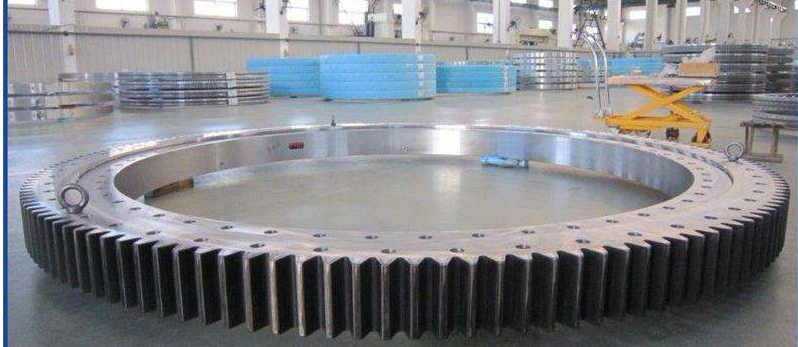
How to choose the material of the large gear ring of the drum dryer?

The large gear ring of the drum dryer plays a very important role in the entire dryer transmission system. The quality of the large gear ring directly affects the operation and life of the dryer. To choose a good quality large gear ring, you need to understand from the following aspects?
Material selection and hardness requirements of the large gear ring of the dryer:
First of all, we need to know the working environment of the dryer gear ring. Therefore, the requirements for large and small gears are higher than those for gears in general transmission mechanisms. The material of the large gear is ZG45, and it is normalized. The surface hardness of the tooth top circle after processing is HB240-270; the material of the small gear is zg45; because the weight of the dryer itself and the weight of the material are not too heavy, in general, the small gear of the small dryer is mostly made of zg45#. While designing, the manufacturer should also make reasonable configuration according to the actual situation.


Common dryer large gear ring parameters are as follows:
0.8m dryer special gear ring modulus 10 teeth 98, 1m dryer special gear ring modulus 12 teeth 107, 1.2m dryer special gear ring modulus 12 teeth 127, 1.4m dryer special gear ring modulus 14 teeth 140, 1.5m dryer special gear ring modulus 14 teeth 130, 1.6m dryer special gear ring modulus 14 teeth 149, 1.8m dryer special gear ring modulus 14 teeth 149, 2m dryer special gear ring modulus 14 teeth 164
Hengchang Heavy Industry Co., Ltd. can design and customize production services according to customer requirements, welcome to consult

How to extend the service life of rollers

As a processing and manufacturing tool, rollers are widely used in factories. Their functions cannot be replaced by other roller products. Of course, the quality requirements for rollers are also very high. After the roller is used for a period of time, various wear problems will occur. In serious cases, the roller may not be able to continue working.
The service life of the roller is generally 8 hours. After that, groove wear and crack fatigue will occur. If the grooves caused by wear are deep, steel sticking and jamming will occur. The plasma aluminum guide roller has obvious resistance to abrasive wear and thermal fatigue. After repairing the roller shaft, the effect is obvious. Plasma cladding technology is used to coat the surface of 45 steel with Al2O3-doped Fe-Ni-based high-temperature anti-wear alloy coating, which can improve the anti-wear and anti-cracking performance of the roller. The application of plasma cladding technology on rollers reduces the labor intensity caused by frequent replacement and reduces the wasted steel rolling work time in disassembly, assembly and transportation of rollers, and can increase the amount of steel rolled, saving a large amount of high-quality steel. At the same time, quality problems caused by roller damage can also be avoided.


From the introduction of the above article, we can know the methods to improve the service life of the rollers, which should be of great help to relevant people. There are many types of rollers on the market. The different materials used to make the rollers will have a great impact on the quality of the rollers and also on the performance of the rollers. For roller manufacturers, roller production needs to be carried out according to formal steps. Improper operation during the production process will greatly affect the quality of the rollers.

What is a herringbone gear and what are the advantages of a herringbone gear?

Helical gears have a lateral force on the axis. In order to eliminate this force, a gear is made into a helical gear with symmetrical opposite directions to eliminate this force. It looks like a herringbone, which is called a herringbone gear for short. Herringbone gears have the advantages of high overlap, small axial load, high load-bearing capacity, and stable operation. The herringbone gear base is used to transmit the torque of the main motor or motor unit to the roller. Herringbone gears cannot be processed by gear shaping or hobbing.
Herringbone gear advantages:


1. Herringbone gears have a high degree of overlap, with at least 2 teeth meshing at any time.
2. The meshing process between the teeth of herringbone cylindrical gears is a transitional process, and the force on the gear teeth gradually increases from small to large, and then from large to small; herringbone gears have high load-bearing capacity and stable operation.
3. Herringbone tooth theory Because the tooth helix angles are in opposite directions in the symmetry direction, there is no or very small axial force.

What are the possible causes of abnormal vibration of the large ring gear of the rotary kiln?

1. Rotary kiln kiln body parts wear and overall sinking. The rotary kiln is a large-load continuous operation equipment. After long-term operation, the rolling ring, supporting wheel, backing plate and other parts wear greatly, and the uneven foundation settlement causes the overall kiln body to settle. decreases, causing the tooth tip clearance to become smaller, causing vibration. Sometimes, although the overall kiln line does not drop, the support position close to the large ring gear drops, which also causes the large ring gear to vibrate. This is due to the foundation of the support position sinking or being severely worn, or due to improper kiln adjustment.
2. Caused by wear of connecting parts. The ring gear is connected to the kiln body through a spring plate pin. The ring gear itself is manufactured in sections and is integrated into a whole by using countersunk screws. After the pins, countersunk screws, and these connecting parts are worn, the ring gear components will loosen and the local ring gear will sink, which will also cause the tooth top clearance to become smaller and cause vibration. From a maintenance perspective, the only solution is to replace (or tighten) the corresponding screws. Of course, for countersunk screws, from the perspective of design and manufacturing, it is better to make the ring gear as a whole (or tightly connected) instead of connecting it with countersunk screws, so as to fundamentally eliminate the vibration cause (large tooth factor). The fact that the flaps are made to be turned over is another issue. Practice has proved that the large ring gear has a simple tooth shape and a low rotational speed. It can still operate normally after half of the tooth thickness is worn).


3. The cylinder at or around the ring gear is bent, causing the large ring gear to deflect excessively in the radial direction and cause vibration. This is manifested in the fact that during the meshing operation of the large ring gear and pinion, the top clearance is smaller for half a turn and smaller for half a turn. The vibration is also a periodic half-vibration. Therefore, the real cause of vibration is that the top clearance is too small.
4. Problems with the ring gear itself. The top clearance of the transmission gear is generally 0.2-0.25 times the module. Due to its large outer diameter and radial deflection of the large ring gear of the rotary kiln, the top clearance is 0.28 times the module plus 0.5-1mm. At the same time, it is required that the radial runout and axial deflection of the large ring gear should not be greater than 2mm after installation. Most of the large ring gears are caused by runout or deflection. Since the large ring gear is connected to the kiln body through the spring plate shaft pin, the large ring gear itself is made into two half rings and combined into a whole with countersunk screws.
5. Vibration caused by tooth thickness wear. The vibration caused by this reason appears as continuous and rhythmic vibration, which can be observed through the meshing of the large ring gear and pinion.
6. The pinion gear is not installed in place. In most rotary kilns, the large ring gear and the two pinion gears form an equilateral triangle in the ideal meshing state, but the angle has changed after long-term operation.

Repair, installation and maintenance methods and techniques for large gears

1. Preparation before maintenance and installation Before repairing and installing the large ring gear, the corresponding tools and equipment should be prepared and their integrity checked. At the same time, understand the working principle and structural characteristics of the ring gear to ensure the smooth progress of the maintenance and installation process.
2. Disassembly and inspection of the ring gear When disassembling the ring gear, the operating procedures should be followed to avoid damaging other components. After disassembly, the ring gear should be comprehensively inspected, including tooth surface wear, cracks, deformation, etc., in order to determine the repair plan.
3. Cleaning and Repair When cleaning the ring gear, appropriate cleaning agents should be used to remove oil stains and impurities. Worn or damaged parts should be repaired, such as welding, grinding, etc.
4. Reinstallation and calibration The repaired ring gear should be reinstalled on the machine and calibrated to ensure that the matching clearance and position of the ring gear and other components are correct.


5. Maintenance methods and cycles Routine maintenance of the ring gear includes lubrication, tightening, etc. Appropriate maintenance cycles and methods should be formulated based on the working conditions of the machine and the material of the ring gear to ensure the normal operation of the ring gear.
6. Regular inspection and records The ring gear should be inspected regularly and the inspection results should be recorded. If any abnormality is discovered, it should be handled and recorded in time.
7. Abnormal situation handling: When an abnormal situation is found in the ring gear, the machine should be stopped immediately for inspection, the cause should be found out and corresponding measures should be taken. If you need to replace the ring gear, you should choose a new ring gear with the same specifications and material as the original ring gear.
8. Maintenance safety precautions During the repair, installation and maintenance of the ring gear, safe operating procedures should be followed to ensure the safety of personnel and equipment. At the same time, qualified parts and lubrication should be used
oil, avoid using inferior products or substitutes.
To sum up, for the repair, installation and maintenance of large ring gears of industrial machinery, we should make full preparations, follow operating procedures, conduct regular inspections and maintenance, and when abnormal conditions are discovered
Deal with it promptly. Only in this way can the normal operation of the ring gear be ensured and the service life and working efficiency of the machine be improved.

The Processing Technology and Application Fields of Shafts

Roller shafts, gear shafts and large machinery non-standard parts are indispensable key components in modern industry. They play a vital role in their respective fields of application, ensuring product quality and performance through precise machining processes.

Rollers are widely used in steel, petroleum, chemical industry, machinery manufacturing and other industries, and withstand the test of heavy load and high-speed operation. Its processing technology involves steps such as material selection, heat treatment, cutting and surface treatment to ensure that the roller has sufficient strength and wear resistance.
As an important component in the mechanical transmission system, the gear shaft is responsible for transmitting power and torque. The processing process includes forging, heat treatment, finishing and gear grinding to achieve high-precision gear shape and Surface Quality. The addition of gear shafts requires strict compliance with technical specifications and standards to ensure transmission efficiency and stability.


Non-standard parts of large machinery are customized according to the special needs of customers and have unique structures and sizes. The processing technology is flexible and diverse, and may involve CNC machining, laser cutting, stamping and other technologies. The processing of non-standard parts requires full consideration of material, process and performance requirements to meet the specific needs of customers. These products play an irreplaceable role in their respective fields. Whether it is the load-bearing and transmission functions of rollers, the transmission function of gear shafts, and customized solutions for non-standard parts of large machinery, they all provide for the development of modern industry. strong support.

Casting process for large ring gear

The casting process of large gears from professional manufacturers is a delicate and complex project. Starting from the drawings provided by the customer, the technical team will conduct detailed analysis and simulation to ensure the feasibility of the casting process.

Mold making is the first step in casting. According to the design drawings, the mold is carefully prepared using wood molds, sand molds, etc. During the melting and casting process, technicians strictly control the chemical composition and addition of various elements to meet the performance requirements of the gears. During the pouring process, temperature, speed and time are precisely controlled. Make sure there are no bubbles, no inclusions inside the casting, and uniform density. Large-scale casting processing manufacturers will demould the large gear after cooling, and then perform cleaning work such as grinding and sand cleaning to remove surface debris and burrs. Gears also need to undergo heat treatment, such as normalizing, annealing, quenching, tempering, etc., to improve the material structure and improve mechanical properties.

In the finishing stage, the gears undergo turning, milling, grinding and other processes to achieve the required dimensional tolerance and surface roughness requirements. Every step of production is accompanied by strict quality inspection, including
Dimensional inspection, appearance inspection, chemical composition analysis, mechanical property testing, etc. ensure that the final product meets quality standards. Professional manufacturers produce high-quality large gears through advanced casting techniques and strict quality control, providing reliable transmission components for mechanical equipment, automobiles, aerospace and other fields.

What is the working temperature that the slewing bearing is suitable for?

As an important component in the mechanical system, the slewing bearing undertakes the important tasks of supporting rotating parts, transmitting force and bearing load. Whether it can adapt to the requirements of different temperatures and working environments directly affects the stability of the equipment’s operation. The slewing bearing is a very important part in the machine. Basically every machine is indispensable for this part. Because this part is relatively fragile, it can also be regarded as a kind of consumables. You need to buy it frequently to maintain the good condition of the machine. normal operation. Let’s follow the slewing drive editor to see what the working temperature the slewing bearing is suitable for.

slewing bearing

The slewing bearing can work normally at -300C ~ +700C. If the user needs to adapt to a lower or higher temperature slewing bearing, the slewing bearing manufacturer can make a special design. If the slewing bearing is used in a particularly harsh environment, such as marine climate, dust or abrasive particles, sand, cement, coal powder, etc. Special sealing rings, protective devices, and appropriate oil passages must be selected. Therefore, in order to ensure that your support can function normally, you hope to do a good job in daily care and maintenance.

The tooth surface of the slewing bearing should be cleaned and oil changed every 8-10 working days, and no foreign matter should be mixed with it.

What are the installation methods and precautions for slewing bearing?

The slew bearing is one of the common key components in industrial equipment. The correct installation has an important impact on the operating stability and life of the equipment. However, because the installation process involves multiple steps and complex technical requirements, it is necessary to strictly follow certain methods and precautions during the installation process. This article will introduce the installation methods and installation precautions of the rotary support bearing to help readers perform the installation operation correctly to ensure the normal operation and safety of the equipment.

1. The way to turn the bearing bearing bearing support method

1. Preparation: Before starting installation, prepare the required tools and equipment, including lifting equipment, measurement tools, lubricating fat, etc. At the same time, check the state of the bearing and installation position to ensure that the surface is smooth, no damage and impurities.

2. Determine the installation location: According to the design drawings and requirements of the equipment, determine the installation location of the rotary support bearing, and make the necessary preparations at this location, such as cleaning and flattening.

3. Installation base: If you need to install a base, fix the base to the installation position and adjust the level instrument to ensure that the level of the base is stable.

4. Installation Bearing: Put the rotary support for the bearing in the installation hole of the base or equipment to ensure that the bearings are fully matched with the base or installation hole, and the surface of the base or installation hole is well exposed to the bearings.

5. Adjust position: Use the measurement tool to check the installation position and position of the bearings to ensure that the bearings are in the correct position and angle. Make fine -tuning as needed until the required installation accuracy.

6. Fixed bearing: After the position of the bearing is correct, use bolts or other fixed parts to fix the bearing firmly on the base or installation hole to ensure that the bearings will not move or shake during the use process.

7. Lubrication: After the installation is completed, add an appropriate amount of lubricating fat or lubricating oil according to the requirements and use environment of the bearings to ensure the lubrication and cooling effect of the bearing during operation.

8. Check: After completing the installation, perform the final check and adjustment of ZUI to ensure that the bearing is installed correctly, fixed firmly, no loose or deviation, and can operate normally.
Slewing ring
2. Precautions for the installation of the rotary support bearing bearing

1. Select the right installation tool: During the installation process, select the right lifting equipment and fixed tools to ensure that the installation operation can be safely and stable.

2. Pay attention to the installation environment: When installing, pay attention to the cleaning and quietness of the environment, avoid interference caused by debris and noise to the installation process, and affect the quality of installation.

3. Installation strictly in accordance with regulations: During the installation process, operate strictly in accordance with the design requirements and installation steps of the equipment, and shall not change or omit any steps at will.

4. Bearing lubrication: When adding lubricating fat or lubricating oil, pay attention to choosing the right lubricant and ensure the smoothness and effectiveness of the lubricating system to extend the service life of the bearing.

5. Installation accuracy: Pay attention to maintaining the installation accuracy of the bearings when installing, and minimize the installation error to ensure the normal operation and stability of the equipment.

6. Prevent damage: During the installation process, be careful of the surface of the bearing and installation position to avoid collision and damage, and ensure the integrity and stability of the installation.

7. Quality inspection: After completing the installation, perform the necessary quality testing and testing to ensure that the quality of the bearing installation meets the requirements and can operate normally.

8. Safety: In the entire installation process, we must always put safety in the first place, strictly abide by the safety operation regulations, and ensure that the installation process is safe and reliable.

In summary, the installation of the rotary support bearing bearing is not only related to the performance and life of the equipment, but also directly affects production efficiency and safety production. Through the installation methods and precautions described in this article, readers can more clearly understand the installation process of the rotary support bearing, and avoid common installation errors and errors in practical operation. In future work, we should continue to pay attention to the details and quality of installation operations, continuously improve the level of installation technology, and ensure the stable operation and safety production of the equipment.

The working principle and function of external tooth turntable bearing

The external tooth rotor bearing is an important mechanical element that includes the outer ring, the inner ring, the rolling body, and the holder. The bearing space is formed between the outer ring and the inner ring, while the rolling body is filled with this space, usually a sphere or a roller. The role of maintaining the frame is to fix the position of the rolling body to ensure that its relative position is stable. This simple and effective design provides a reliable structural basis for the external tooth rotor bearings. The specific work principle of the specific external tooth turntable bearing is explained in detail.

1. The working principle of the outer tooth turntable bearing

1. Rolling friction mechanism

The working principle of the external tooth rotor bearing mainly depends on the mechanism of rolling friction. When the external force acts on one of the inner and outer ring, the rolling body begins to roll between them instead of sliding. This rolling friction method effectively reduces the friction in the bearings and improves the efficiency of the bearings. In this way, the outer tooth rotor bearing can maintain a relatively low friction coefficient under high -speed rotation, reducing energy loss.

2. Sliding friction

The working principle of the external tooth rotor bearing also includes the adaptability of sliding friction. When the bearing is at a low speed or stopped state, the rolling body may switch to the sliding friction mode. In this case, the rolling body slides along the surface of the inner ring or the outer ring to produce friction. However, through the use of lubricants, sliding friction can still be effectively controlled to reduce energy loss and prolong the life of the bearings. Lubricants play a key role in maintaining the normal operation of the outer tooth rotor bearing.
Rotor bearing
2. The role of the external tooth rotor bearing

The working principle of the external tooth rotor bearing determines its role in various industrial fields. This bearing structure is simple and reliable, making it a key component in the mechanical system. In engineering design, external tooth rotor bearing is often used to support rotating components, such as turntables, wheels, robotic arms, etc.

In the automotive industry, the external tooth rotor bearing is widely used in the wheel bearing system, providing a stable driving and reliable control to the vehicle. In addition, it also plays a key role in high -demand fields such as wind power generation and aerospace equipment.

In general, the working principle of the outer tooth rotor bearing is cleverly used by the method of rolling friction and sliding friction to realize the support and transfer load under various operating conditions. This makes it one of the indispensable key components in modern mechanical systems.