6 major considerations for purchasing non-standard customized gears

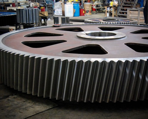
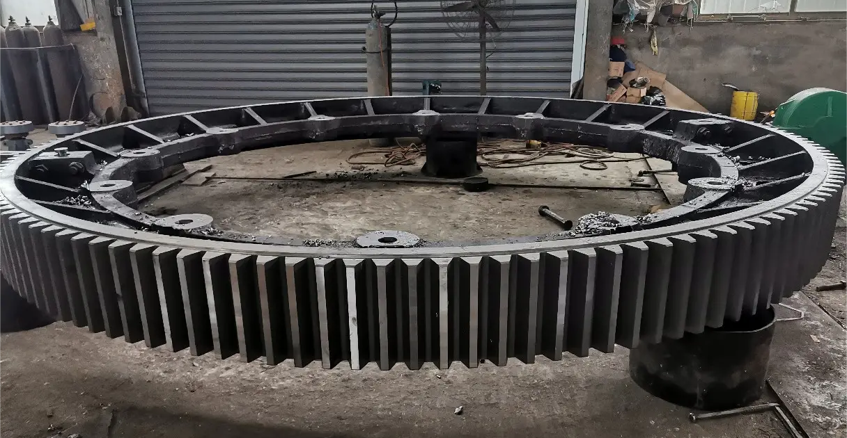
Gears are an important part of mechanical transmission and there are many types of them. Among them, non-standard gear customization has gradually become the mainstream of the market. However, if we accidentally choose unqualified products during the purchase process, it will bring great troubles to our work and life. In order to help everyone avoid these problems, this article will introduce you to the 6 major considerations for purchasing non-standard gear customization.
1. Quality must be guaranteed
When purchasing non-standard customized gears, the first thing to consider is its quality. A high-quality gear should have the characteristics of high strength, wear resistance, and low noise. Therefore, before choosing, be sure to check the supplier’s production process and quality management system to ensure that its products meet relevant standards and requirements.
2. Ensure accurate size
Non-standard gear customization often needs to be designed and manufactured according to different usage requirements. Therefore, when purchasing, pay special attention to the dimensional accuracy of the gear. If the size is inaccurate, it will lead to assembly difficulties or poor transmission effect. Therefore, we should choose suppliers with advanced equipment and rich experience to ensure the dimensional accuracy of the product.


3. Understand the material characteristics
The material of the gear directly affects its service life and use effect. When choosing non-standard gears, we should understand the characteristics and applicable scenarios of different materials. Common materials include alloy steel, stainless steel, cast iron, etc. Each material has its advantages and disadvantages. We need to choose the right material according to actual needs.
4. Consider transmission efficiency
When purchasing non-standard customized gears, we also need to consider their transmission efficiency. The transmission efficiency depends on the tooth shape and number of teeth of the gear. When purchasing, we should ensure that the design of the gear can achieve high transmission efficiency to improve the overall working efficiency of the mechanical equipment.


5. Check the experience of process engineers
Non-standard gear customization requires experienced process engineers to complete. They can design and manufacture gears according to specific usage requirements and working environment. Therefore, before purchasing, we should understand the supplier’s process engineer team, understand their experience and strength, to ensure the quality and performance of the product.
6. Confirm after-sales service
We also need to carefully consider the supplier’s after-sales service. Gears are important components in mechanical equipment. If there are quality problems or other failures, after-sales service will play a vital role. When purchasing, we should choose suppliers who provide comprehensive after-sales service to obtain timely repairs and support.
Through the above 6 precautions, we can more accurately choose non-standard gear customized products that meet our needs. Be cautious when choosing suppliers and conduct multiple inspections to ensure that you purchase high-quality products and services. I hope this article is helpful to you. Thank you for reading!

How are gears classified?

Introduction to typical forging methods and process flow of large steel forgings

Large steel forgings generally refer to products with ingot weight ≥150t and single forging weight ≥90t. The representative grades are generally 25Cr2Ni4MoV, 30Cr2Ni4MoV, 40Cr3MoV, 45Cr4NiMoV, 12Cr2Mo1, 12Cr2Mo1V, 20MnNiMo and other grades of forging materials. Large steel forgings are generally used to manufacture the main components of industrial equipment such as power, shipbuilding, metallurgy, and petrochemicals. Because they are used as main components, the performance and quality requirements of large steel forgings are generally extremely strict, and the forging method and process of steel forgings play a decisive role in performance and quality.

In my country, there are three processing standards for large steel forgings, namely GB/T 37464-2019 “Quenching and tempering of large steel forgings”, GB/T 37558-2019 “Post-forging heat treatment of large steel forgings”, and GB/T 37559-2019 “Normalizing and annealing of large steel forgings”. These three standards play a major role in guiding the processing technology of large steel forgings. Only by mastering the basic forging methods and process flow of steel forgings can we better break through and develop new processes. Therefore, it is necessary to understand the typical forging methods and process flow of large steel forgings.
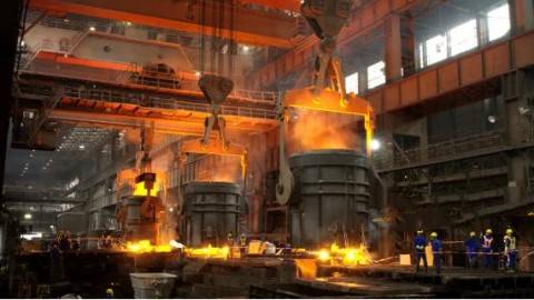
For large steel forgings, the main purpose of forging is to form and improve the internal defects and organization of the material to ensure the shape and size of the forgings and improve the internal quality. There are four common typical forging methods, namely wide flat anvil high temperature strong pressure method (WHF forging method), center compaction method, center tensile stress free forging method (FM forging method), wide large anvil compaction forging method (KD forging method). The process flow is divided into large shaft process flow, cylinder forging process flow, and pancake forging process flow according to the type of forging. The following is a detailed introduction to the relevant methods or processes.

1. Wide flat anvil high temperature strong pressure method (WHF forging method)

Wide flat anvil high temperature strong pressure method (WHF forging method) is a forging process method that uses high temperature and large deformation conditions on a wide flat anvil to forge the porosity defects in the steel ingot. During processing, it is recommended to use an anvil width ratio of 0.6 to 0.8 and a reduction rate of about 20%. Under this parameter, the stress and strain distribution in the billet is more reasonable, and the center, pores and loose structures will be effectively compacted. There should be about 10% overlap of the anvil width in the middle of the two pressed parts, and pay attention to the staggered anvil when turning and pressing, so as to achieve the purpose of uniform compaction of the billet.

2. Center compaction method

The center compaction method is to chamfer the steel ingot, forge it into a square cross-section billet, and then heat it to 1220℃~1250℃ (initial forging temperature) and keep it warm. Then take it out of the furnace and use surface air cooling, blast or spray cooling to 720℃~780℃ (final forging temperature). A layer of “hard shell” is formed on the surface of the steel ingot. At this time, the temperature of the core of the steel ingot is still maintained at 1050℃~1100℃, and the temperature difference between the inside and outside is about 230℃~270℃. Use a narrow flat anvil to pressurize the steel ingot longitudinally, and use the wrapping effect of the surface low-temperature hard shell to achieve the purpose of significantly compacting the core.


3. Center tensile stress-free forging method (FM forging method)
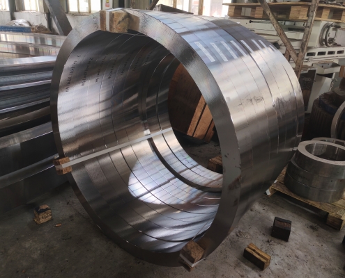
The center tensile stress-free forging method (FM forging method) is that the lower anvil is a wide flat anvil and the upper anvil is a narrow anvil. The billet deforms between the asymmetric flat anvils, and asymmetric deformation occurs inside the forging billet, and the stress state of each part also changes. When the billet is deformed, the part that forms tensile stress moves to the bottom of the billet, while the central part is subjected to compressive stress, which has a significant effect on the internal pore defects of the forged steel ingot. The recommended process parameters of the FM forging method are an upper anvil width ratio of 0.6 and a reduction rate of 14% to 15%.

4. Wide anvil compaction forging method (KD forging method)

The upper and lower anvils of the wide anvil compaction forging method (KD forging method) are both V-shaped anvils. Taking advantage of the fact that the steel ingot has sufficient plasticity under long-term high temperature conditions, it can be forged with a wide anvil and a large reduction rate on limited equipment. The use of upper and lower V-shaped anvils for forging is conducive to improving the metal plasticity of the forging surface, increasing the three-dimensional compressive stress state of the core, ensuring the concentricity of the forging, and effectively forging the internal defects of the steel ingot. The process parameters here recommend the upper and lower V-shaped anvil opening angle α=135°, the anvil width ratio of 0.4~0.8 (the best is 0.6), and the reduction rate of about 20%. When forging, attention should be paid to staggering the anvil and turning it 90° to ensure uniform compaction of the core of the forging and high drawing efficiency.
5. Introduction to the process flow of different forged steel parts

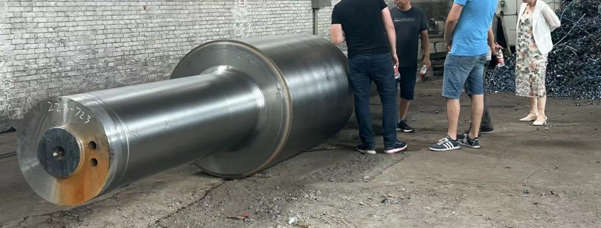
(1) The process flow of large shaft forgings is: clamping jaws → main deformation → material separation → finished product. The main deformation can be carried out by wide flat anvil high temperature strong pressure method, center compaction method, center tensile stress free forging method, wide anvil compaction forging method, or other suitable forging methods to ensure that the forging has a sufficient forging ratio and that the entire cross section is fully forged. If the cross-sectional size of the forging is large, the forging ratio can be increased by increasing the number of upsetting and drawing times, or other methods can be used to increase the forging ratio.

(2) The process flow of large cylindrical forgings is generally: blanking → upsetting → punching → hole expansion. For long large cylindrical forgings, the mandrel drawing process can be added after punching. In order to ensure that the forging has a sufficient forging ratio, the forging ratio can be increased by increasing the drawing or upsetting and drawing before blanking, or other methods can be used to increase the forging ratio.

(3) The process flow of large pancake forgings is generally: jaw pressing → main deformation → blanking → upsetting, expansion. The main deformation of pancake forgings can refer to the process flow of large shaft forgings. After the pancake hollow forgings are upset and expanded, punching procedures should be added. When expanding pancake forgings, reasonable expansion methods can be used to ensure the compaction effect and uniform deformation of pancake forgings.

The above is an introduction to the common forging methods and process flow of large forged steel parts. Quality assurance technology is very important in the manufacturing of large forged steel parts, but large forged steel parts are typically multi-variety and small-batch production, so in many cases, it is difficult for enterprises to realize automated processing for their forging production. The forging process of large forged steel parts is a systematic process, which also requires us to master the forging equipment and accessories operation process, the ingot performance meets the requirements, and the risk control of the forging process. All of this requires us to reasonably select the forging deformation scheme and the distribution of deformation amount of each fire according to the actual production and operation, the internal quality requirements of the enterprise, and the actual scientific research results.
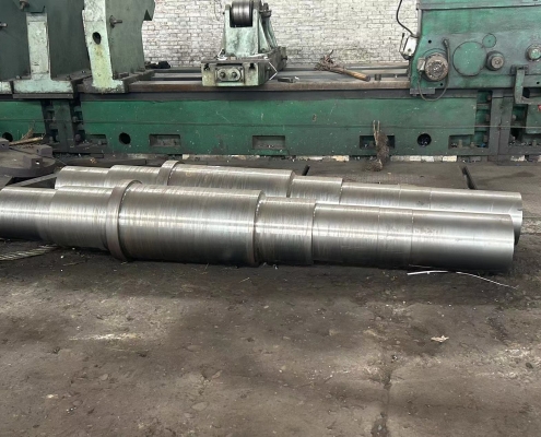
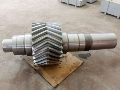
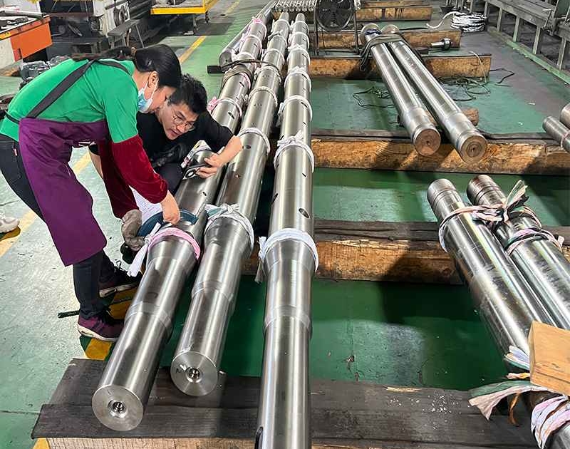
Gear shaft processing technology analysis – processing sequence arrangement

The machining sequence is arranged according to the principle of base surface first, rough first then fine, main first then secondary. For general parts of gear shaft, after the center hole is prepared, the outer circle is processed first, and then other parts are processed, and it is important to separate rough and fine processing. In the gear shaft processing technology, heat treatment is used as a sign, rough processing before quenching and tempering treatment, semi-finishing before quenching treatment, and fine processing after quenching. After separating the stages in this way, the fine processing of the main surface is guaranteed, and the stress during processing of other surfaces will not affect the accuracy of the main surface.
When arranging the order of gear shaft processes, the following points should also be noted.


(1) The rough machining of the tooth profile of the shaft should be arranged after the semi-finishing of the outer circles of the gear shaft. Because the gear shaft has a relatively large workload and is difficult to process, the processing position should be appropriately placed a little later to increase the positioning height of the positioning reference. The tooth profile finishing should be arranged after all the outer circles of the part are processed, so as to eliminate the heat treatment deformation caused by the local quenching of the tooth profile.
(2) The processing sequence of the outer circle surface should be to process the large diameter outer circle first, and then the small diameter outer circle, so as not to reduce the rigidity of the workpiece at the beginning.
(3) The processing of secondary surfaces such as keyways on gear shafts should generally be arranged after the outer circle finishing or rough grinding and before the outer circle finishing. If the keyway is milled before finishing, on the one hand, before finishing, the vibration caused by intermittent cutting will affect the processing quality and easily damage the tool; on the other hand, the size requirements of the keyway are also difficult to guarantee. These surface processing should not be arranged after the main surface finishing, so as not to damage the main surface accuracy.

Casting of gear rings and gears and how to repair damaged gear rings?

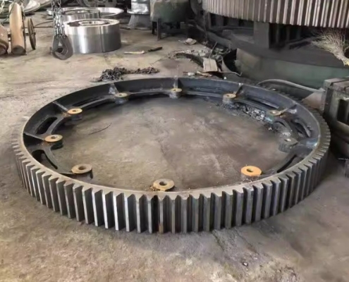
Large gear rings are important and indispensable parts of equipment, just like gears. Although the two are similar, their main function is to transmit and change the direction of force. However, in addition to this, the protection of the main body of the machine system by the drive of the gear ring cannot be ignored.
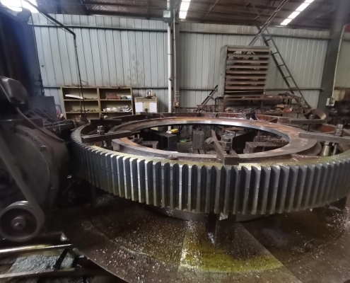
The outer teeth of the large gear ring are divided into two types of tooth shapes: drum teeth and straight teeth. It can change the contact conditions of the teeth and improve the ability to transmit torque, thereby meeting the requirements of cost protection and extending the service life. The large gear ring is a thin-walled ring forging. It is easy to have problems such as uneven wall thickness, folding, and ellipse during the forging process. Therefore, the quality of the casting can be improved by controlling the details of the casting process.
Therefore, it can be said that the large gear ring is a very important component for protecting the service life of the machine. So when the large gear is damaged, how should we repair it?

First, the steel castings should be processed. Different processing methods should be used for large gears with different degrees of damage, and the damaged parts of the large gear ring should be processed;

Then, welding should be carried out. Before welding, it should be noted that there should be no impurities such as dirty oil, rust, slag, etc. near the welding part, otherwise it will affect the welding effect;

After the welding treatment, there may still be relatively small pores or sand holes on the surface of the steel casting. After removing these defects, the area should be repaired.

After the welding treatment, the damaged large gear ring can be used normally again, which not only saves the production cost of the enterprise, but also helps to reduce the loss of resources, which can be said to kill two birds with one stone.

About gear transmission types and fault response methods

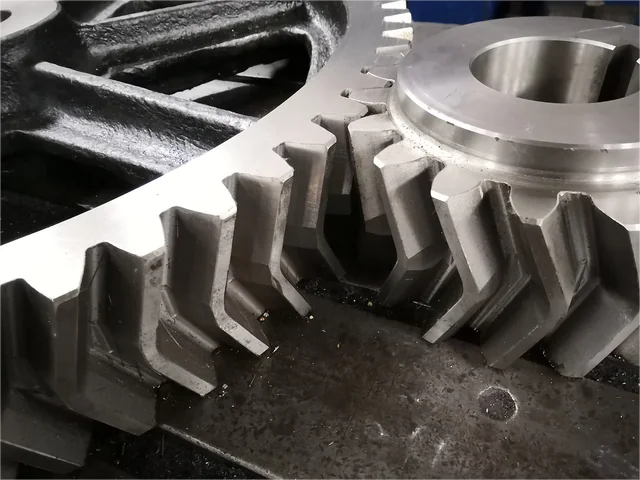
When manufacturing gears, several typical errors such as eccentricity, pitch error, base pitch error and tooth profile error are usually generated. There are many reasons for gear manufacturers to generate these errors, including errors from machine tool movement, cutting tool errors, errors from improper installation and debugging of tools, workpieces, and machine tool systems, fixture errors, and gear deformation caused by internal stress during heat treatment. When these gear errors are large, it will cause the gear transmission to rotate slowly and quickly with micro-inertia interference, causing impact and vibration when the gear pair is meshed, causing large noise.

Due to assembly technology and assembly methods, the assembly error of “one end in contact and one end hanging” is usually caused when assembling gears; linear deviation of gear shaft and imbalance of gears, etc. One-end contact or linear deviation of gear shaft will cause uneven load on the gear, causing excessive load on individual gear teeth, causing local early wear, and even causing gear tooth breakage in severe cases. Gear imbalance will cause impact vibration and noise.
1. Tooth fracture
During gear transmission, the action force of the driving gear and the reaction force of the driven gear both act on the other gear teeth through the contact point. The dangerous situation is that the contact point is located at the top of the gear teeth at a certain moment; at this time, the gear teeth are like a cantilever beam. The bending stress generated at the root of the gear teeth after being loaded is large. If it is suddenly overloaded or impact overloaded, it is easy to cause overload fracture at the root of the gear teeth.
2. Tooth surface wear or scratches
Gear teeth have relative sliding during meshing transmission, coupled with poor lubrication, unclean lubricating oil, lubricating oil deterioration, low speed heavy load or poor heat treatment quality, which can cause adhesive wear, abrasive wear, corrosive wear and scratches on the gear tooth surface.
3. Tooth surface fatigue
The so-called tooth surface fatigue mainly includes pitting and peeling of the tooth surface. The cause of pitting is mainly due to the micro fatigue cracks caused by the pulsating contact stress on the working surface of the gear teeth. When the lubricating oil enters the surface crack area, it first closes the entrance and then squeezes during the meshing process. The lubricating oil in the micro fatigue crack area expands the crack area on the gear tooth surface under high pressure, causing the surface metal particles to fall off from the tooth surface, leaving small pits to form pitting on the tooth surface. When the fatigue crack on the gear tooth surface continues to expand deeper and farther, it will cause a large area or large pieces to fall off, forming tooth surface spalling.
4. Plastic deformation of tooth surface
When the gear material is soft and the load transmitted is large, plastic deformation of the tooth surface is easy to occur. Under the action of excessive friction between the tooth surfaces, the contact stress of the tooth surface will exceed the material’s anti-extrusion yield limit, and the tooth surface material will enter a plastic state, causing plastic flow of the tooth surface metal. This causes the active gear to form grooves on the tooth surface near the pitch line, and the driven gear to form ridges on the tooth surface near the pitch line, thereby destroying the tooth shape.

New progress in the manufacturing and application of large-scale mechanical rollers

New progress in the manufacturing and application of large-scale mechanical rollers: Safety production and industry exchanges are equally important. Recently, a series of new progress has been made in the field of large-scale mechanical roller manufacturing, which not only improves production efficiency, but also expands the application field, and also puts forward higher requirements for safety production.
In terms of manufacturing, the application of new materials makes the rollers have higher strength and wear resistance, and increases the service life of the product. At the same time, advanced manufacturing technology also reduces energy consumption and emissions in the production process, reflecting the concept of green environmental protection.
In terms of application fields, large-scale mechanical rollers are not only widely used in traditional textile, food, medicine and other industries, but also gradually expand to emerging fields such as new energy and environmental protection. Its efficient and stable performance provides strong support for the development of these industries.


Safety production has always been the top priority of the roller manufacturing industry. Recently, the industry has strengthened safety production training and improved employees’ safety awareness and operating skills. At the same time, by introducing advanced safety monitoring equipment and technical means, the safety risks in the production process have been effectively reduced.
In addition, exchanges and cooperation within the industry are becoming more and more frequent. By holding seminars, exhibitions and other activities, enterprises and research institutions are able to share the latest technological achievements and market trends, which has promoted the rapid development of the entire industry.
Looking into the future, the large-scale mechanical roller manufacturing industry will continue to adhere to the development concept of innovation, greenness and safety, continuously improve product quality and application level, and make greater contributions to promoting the transformation and upgrading of my country’s manufacturing industry.

New progress in the manufacturing and application of large-scale mechanical rollers

Recently, a series of new progress has been made in the field of large-scale mechanical roller manufacturing, which not only improves production efficiency, but also expands the application field, and also puts forward higher requirements for safe production.
In terms of manufacturing, the application of new materials makes the rollers have higher strength and wear resistance, and increases the service life of the product. At the same time, advanced manufacturing processes also reduce energy consumption and emissions in the production process, reflecting the concept of green environmental protection. In terms of application fields, large-scale mechanical rollers are not only widely used in traditional textile, food, medicine and other industries, but also gradually expand to emerging fields such as new energy and environmental protection. Its efficient and stable performance provides strong support for the development of these industries.


Safe production has always been the top priority of the roller manufacturing industry. Recently, the industry has strengthened safety production training and improved employees’ safety awareness and operating skills. At the same time, by introducing advanced safety monitoring equipment and technical means, the safety risks in the production process have been effectively reduced.
In addition, exchanges and cooperation within the industry are becoming more and more frequent. By holding seminars, exhibitions and other activities, enterprises and research institutions are able to share the latest technological achievements and market trends, which has promoted the rapid development of the entire industry.
Looking into the future, the large-scale mechanical roller manufacturing industry will continue to adhere to the development concept of innovation, greenness and safety, continuously improve product quality and application level, and make greater contributions to promoting the transformation and upgrading of my country’s manufacturing industry.

Why are most gears forged instead of cast now?

In the past, gears were usually made by casting, but now more and more gears are produced by forging.

1. Forging can provide higher strength and toughness. Gears are subjected to huge pressure and load during operation, so their materials must have sufficient strength and durability. In contrast, gears made by casting usually have internal defects and holes, which reduce the strength and toughness of the gears. The forging process can plastically deform the metal raw materials by heating and hammering, eliminate internal defects, and make the gear materials have higher strength and toughness.

2. Forging can provide higher precision and quality. During the casting process, liquid metal is filled through the mold and cooled and solidified, which may cause uneven shrinkage or deformation of the gear surface. These deformations affect the precision and quality of the gear. In the forging process, by heating and hammering the metal, the metal raw materials can be uniformly plastically deformed, thereby ensuring the precision and quality of the gear.

3. Forging can also save materials and costs. During the casting process, due to the free flow of liquid metal, a certain degree of waste will be generated. The forging process, on the other hand, presses the metal raw material into the desired shape without the need for additional material consumption. In addition, the forging process can also reduce production costs by reducing subsequent processing steps, such as reducing milling, grinding and other operations.

Fourth, the forging process also has the advantage of environmental protection. In the casting process, a large amount of fuel is often required to heat the metal, and a large amount of waste gas and waste slag is generated. The forging process can plastically deform the metal raw material by heating and hammering, and does not require a large amount of fuel, thereby reducing pollution to the environment.

Therefore, the forging process provides higher strength and toughness, higher precision and quality, material and cost savings, and environmental advantages. Therefore, the current forging process will play an increasingly important role in gear manufacturing.