Archive for year: 2024
What are the two methods for processing helical internal gear rings?Grinding and milling
/in Industry News /by hgb-bearingIntroduction to typical forging methods and process flow of large steel forgings
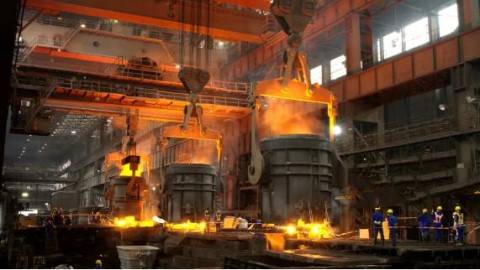
/in Industry News /by hgb-bearingLarge steel forgings generally refer to products with ingot weight ≥150t and single forging weight ≥90t. The representative grades are generally 25Cr2Ni4MoV, 30Cr2Ni4MoV, 40Cr3MoV, 45Cr4NiMoV, 12Cr2Mo1, 12Cr2Mo1V, 20MnNiMo and other grades of forging materials. Large steel forgings are generally used to manufacture the main components of industrial equipment such as power, shipbuilding, metallurgy, and petrochemicals. Because they are used as main components, the performance and quality requirements of large steel forgings are generally extremely strict, and the forging method and process of steel forgings play a decisive role in performance and quality.
In my country, there are three processing standards for large steel forgings, namely GB/T 37464-2019 “Quenching and tempering of large steel forgings”, GB/T 37558-2019 “Post-forging heat treatment of large steel forgings”, and GB/T 37559-2019 “Normalizing and annealing of large steel forgings”. These three standards play a major role in guiding the processing technology of large steel forgings. Only by mastering the basic forging methods and process flow of steel forgings can we better break through and develop new processes. Therefore, it is necessary to understand the typical forging methods and process flow of large steel forgings.
For large steel forgings, the main purpose of forging is to form and improve the internal defects and organization of the material to ensure the shape and size of the forgings and improve the internal quality. There are four common typical forging methods, namely wide flat anvil high temperature strong pressure method (WHF forging method), center compaction method, center tensile stress free forging method (FM forging method), wide large anvil compaction forging method (KD forging method). The process flow is divided into large shaft process flow, cylinder forging process flow, and pancake forging process flow according to the type of forging. The following is a detailed introduction to the relevant methods or processes.
1. Wide flat anvil high temperature strong pressure method (WHF forging method)
Wide flat anvil high temperature strong pressure method (WHF forging method) is a forging process method that uses high temperature and large deformation conditions on a wide flat anvil to forge the porosity defects in the steel ingot. During processing, it is recommended to use an anvil width ratio of 0.6 to 0.8 and a reduction rate of about 20%. Under this parameter, the stress and strain distribution in the billet is more reasonable, and the center, pores and loose structures will be effectively compacted. There should be about 10% overlap of the anvil width in the middle of the two pressed parts, and pay attention to the staggered anvil when turning and pressing, so as to achieve the purpose of uniform compaction of the billet.
2. Center compaction method
The center compaction method is to chamfer the steel ingot, forge it into a square cross-section billet, and then heat it to 1220℃~1250℃ (initial forging temperature) and keep it warm. Then take it out of the furnace and use surface air cooling, blast or spray cooling to 720℃~780℃ (final forging temperature). A layer of “hard shell” is formed on the surface of the steel ingot. At this time, the temperature of the core of the steel ingot is still maintained at 1050℃~1100℃, and the temperature difference between the inside and outside is about 230℃~270℃. Use a narrow flat anvil to pressurize the steel ingot longitudinally, and use the wrapping effect of the surface low-temperature hard shell to achieve the purpose of significantly compacting the core.
3. Center tensile stress-free forging method (FM forging method)
The center tensile stress-free forging method (FM forging method) is that the lower anvil is a wide flat anvil and the upper anvil is a narrow anvil. The billet deforms between the asymmetric flat anvils, and asymmetric deformation occurs inside the forging billet, and the stress state of each part also changes. When the billet is deformed, the part that forms tensile stress moves to the bottom of the billet, while the central part is subjected to compressive stress, which has a significant effect on the internal pore defects of the forged steel ingot. The recommended process parameters of the FM forging method are an upper anvil width ratio of 0.6 and a reduction rate of 14% to 15%.
4. Wide anvil compaction forging method (KD forging method)
The upper and lower anvils of the wide anvil compaction forging method (KD forging method) are both V-shaped anvils. Taking advantage of the fact that the steel ingot has sufficient plasticity under long-term high temperature conditions, it can be forged with a wide anvil and a large reduction rate on limited equipment. The use of upper and lower V-shaped anvils for forging is conducive to improving the metal plasticity of the forging surface, increasing the three-dimensional compressive stress state of the core, ensuring the concentricity of the forging, and effectively forging the internal defects of the steel ingot. The process parameters here recommend the upper and lower V-shaped anvil opening angle α=135°, the anvil width ratio of 0.4~0.8 (the best is 0.6), and the reduction rate of about 20%. When forging, attention should be paid to staggering the anvil and turning it 90° to ensure uniform compaction of the core of the forging and high drawing efficiency.
5. Introduction to the process flow of different forged steel parts
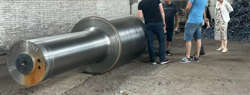
(1) The process flow of large shaft forgings is: clamping jaws → main deformation → material separation → finished product. The main deformation can be carried out by wide flat anvil high temperature strong pressure method, center compaction method, center tensile stress free forging method, wide anvil compaction forging method, or other suitable forging methods to ensure that the forging has a sufficient forging ratio and that the entire cross section is fully forged. If the cross-sectional size of the forging is large, the forging ratio can be increased by increasing the number of upsetting and drawing times, or other methods can be used to increase the forging ratio.
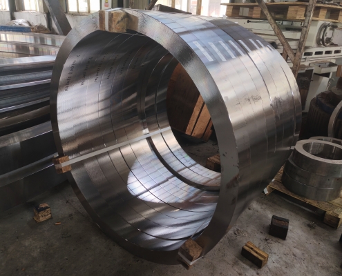
(2) The process flow of large cylindrical forgings is generally: blanking → upsetting → punching → hole expansion. For long large cylindrical forgings, the mandrel drawing process can be added after punching. In order to ensure that the forging has a sufficient forging ratio, the forging ratio can be increased by increasing the drawing or upsetting and drawing before blanking, or other methods can be used to increase the forging ratio.
(3) The process flow of large pancake forgings is generally: jaw pressing → main deformation → blanking → upsetting, expansion. The main deformation of pancake forgings can refer to the process flow of large shaft forgings. After the pancake hollow forgings are upset and expanded, punching procedures should be added. When expanding pancake forgings, reasonable expansion methods can be used to ensure the compaction effect and uniform deformation of pancake forgings.
The above is an introduction to the common forging methods and process flow of large forged steel parts. Quality assurance technology is very important in the manufacturing of large forged steel parts, but large forged steel parts are typically multi-variety and small-batch production, so in many cases, it is difficult for enterprises to realize automated processing for their forging production. The forging process of large forged steel parts is a systematic process, which also requires us to master the forging equipment and accessories operation process, the ingot performance meets the requirements, and the risk control of the forging process. All of this requires us to reasonably select the forging deformation scheme and the distribution of deformation amount of each fire according to the actual production and operation, the internal quality requirements of the enterprise, and the actual scientific research results.
Why should large gear processing be finely produced?
/in Company News /by hgb-bearingThe production of large gears requires special processes to produce products. Are you curious about the specific processes? Here, the gear manufacturer editor will briefly popularize it for everyone:
The large gears of the dryer adopt a unique heat treatment technology in casting to improve the hardness of the gear ring, improve the wear resistance and impact resistance of the product; secondly, the use of high-strength steel casting and the optimization of the rotary kiln ensure the stability of the components under long-term operation and extend the service life of the product during application. Finally, the scale of large gear processing is increased, the technical content is invested, and the mass production of products is carried out with short construction period and excellent quality.
As a member of the transmission system, the large gear is naturally the source of noise, and it transmits noise with the natural frequency and meshing frequency. If we want to reduce the noise as much as possible, then we need to buy large gears.
The processing accuracy of gears will naturally be higher than that of general large gears. The higher the processing accuracy, the lower the noise will be. Although we cannot completely remove the noise, it is an important means of noise reduction.
How to choose cast or forged gears?
/in Company News /by hgb-bearingPeople in the foundry industry know that large gears are transmission parts of mechanical equipment and play a key role in the operation of the entire machine. If the large gear (also called the large gear ring) is worn, it needs to be replaced to delay production. In addition, the large gear is a consumable part. From the user’s point of view, the longer the service life, the better. Therefore, when users choose large gears, they require long life, impact resistance, wear resistance, etc., so the specific selection should be based on the actual situation.
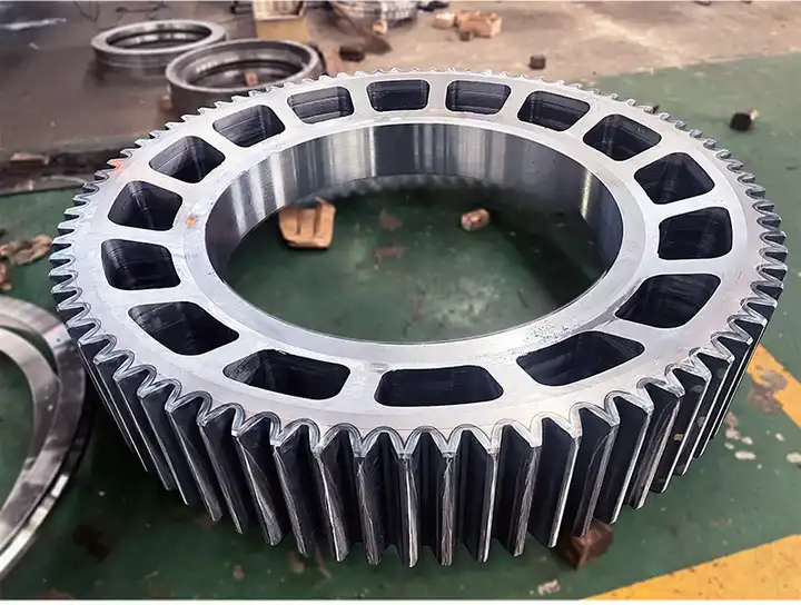
Casting steel manufacturers believe that it is better to use forging technology under normal circumstances if there are high speed requirements and low life requirements for gears, because forged gears have dense texture, hardness and wear resistance than cast steel parts. The large gear with the right performance has a large diameter and low speed, so it is more suitable to cast steel castings, which can meet the needs of long-term rotation of mechanical equipment and save production and maintenance costs.
From the above, I believe that users have a general understanding of this. For gears with small diameters and high speeds, forging production can be selected, and forging production can also be mass-produced. If the diameter is relatively large, you can choose to cast a large gear. If the diameter is too large, you can produce it in two halves and then install the large gear together as required.
Gear shaft processing technology analysis – arrangement of heat treatment process
/in Company News /by hgb-bearingIn the entire process of shaft processing, sufficient heat treatment processes should be arranged to ensure the mechanical properties and processing accuracy requirements of the gear shaft and improve the processing performance of the workpiece.
Generally, normalizing treatment is arranged first after the shaft blank is forged to eliminate forging internal stress, refine the grains, and improve the cutting performance during machining.
Tempering and tempering treatment is arranged after rough machining. In the rough machining stage, most of the machining allowance of the gear shaft is removed after rough turning, drilling and other processes. The cutting force and heat generation during rough machining are very large. Under the action of force and heat, the shaft produces a lot of internal stress. The internal stress can be eliminated through tempering treatment, replacing aging treatment, and the required toughness can be obtained at the same time.
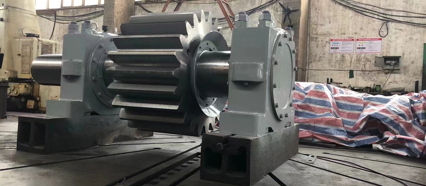
After semi-machining, except for important surfaces, other surfaces have reached the design size. Only finishing allowance is left for important surfaces. At this time, local quenching treatment is arranged on the teeth to meet the designed hardness requirements and ensure the wear resistance of these surfaces. The subsequent finishing process can eliminate quenching deformation.
Gear shaft processing technology analysis – processing sequence arrangement
/in Industry News /by hgb-bearingThe machining sequence is arranged according to the principle of base surface first, rough first then fine, main first then secondary. For general parts of gear shaft, after the center hole is prepared, the outer circle is processed first, and then other parts are processed, and it is important to separate rough and fine processing. In the gear shaft processing technology, heat treatment is used as a sign, rough processing before quenching and tempering treatment, semi-finishing before quenching treatment, and fine processing after quenching. After separating the stages in this way, the fine processing of the main surface is guaranteed, and the stress during processing of other surfaces will not affect the accuracy of the main surface.
When arranging the order of gear shaft processes, the following points should also be noted.
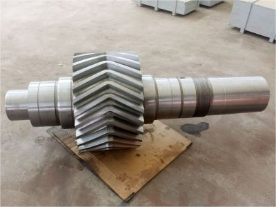
(1) The rough machining of the tooth profile of the shaft should be arranged after the semi-finishing of the outer circles of the gear shaft. Because the gear shaft has a relatively large workload and is difficult to process, the processing position should be appropriately placed a little later to increase the positioning height of the positioning reference. The tooth profile finishing should be arranged after all the outer circles of the part are processed, so as to eliminate the heat treatment deformation caused by the local quenching of the tooth profile.
(2) The processing sequence of the outer circle surface should be to process the large diameter outer circle first, and then the small diameter outer circle, so as not to reduce the rigidity of the workpiece at the beginning.
(3) The processing of secondary surfaces such as keyways on gear shafts should generally be arranged after the outer circle finishing or rough grinding and before the outer circle finishing. If the keyway is milled before finishing, on the one hand, before finishing, the vibration caused by intermittent cutting will affect the processing quality and easily damage the tool; on the other hand, the size requirements of the keyway are also difficult to guarantee. These surface processing should not be arranged after the main surface finishing, so as not to damage the main surface accuracy.
Thickness determines the size of the gear
/in Company News /by hgb-bearingThe main function of the gear is transmission. Why are some gears large and some gears small? Some people may say it is because of the size of the mold, but not all gear moduli are the ratio of pitch to circumference. The larger the modulus, the stronger and thicker the teeth, and the larger the size of the gear. The tooth height of a standard gear is equal to 2.25 times the modulus, and the tooth thickness is equal to 0.5*3.14*modulus, that is, the larger the modulus, the larger the teeth. The modulus is also large, the higher the number of teeth, the thicker the gear teeth, and if the number of teeth is determined, the larger the radial size of the wheel. Gears with larger moduli also have larger numbers of teeth. The modulus determines the size of a single tooth profile, not the size of the gear, and has nothing to do with the pressure angle. The modulus is the largest parameter that affects the gear. This does not mean that the gear is large. This should also be determined according to the use environment. If a small gear should be used in a place, it is definitely not suitable for a large gear. So it is not the bigger the better, the right one is the best.
The diameter of the involute gear is d=zm, which is the modulus multiplied by the number of teeth. The modulus is related to the load-bearing capacity of the gear. When the gear is made of the same material and heat treated, the larger the modulus, the stronger the load-bearing capacity; the number of teeth is related to the transmission ratio. The speed of the gear is related to this number as n1*z1=n2*z2.
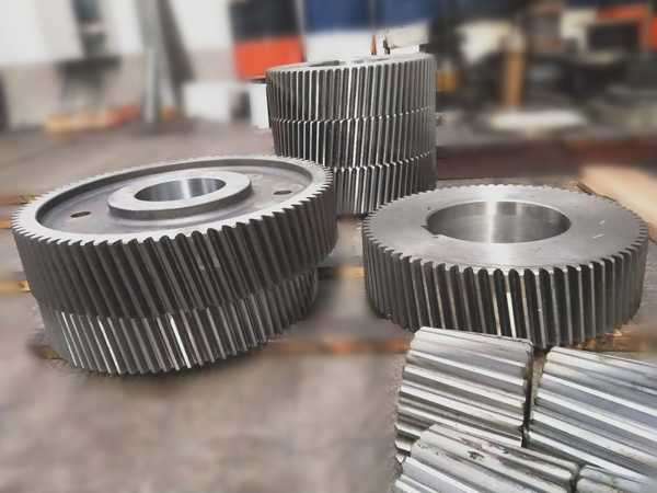
Therefore, there are two factors that determine the size of the gear, the load-bearing capacity and the transmission speed ratio.
Module m
(1) This module is equivalent to the model of the gear, which can determine the size of the gear. Other parameters are the same. The larger the module, the larger the size of the gear.
Number of teeth z
(2) Needless to say, the number of teeth is the number of teeth in the gear. This is related to the gear ratio. The two meshing gears are in the best possible state.
Pressure angle α
(3) The pressure angle usually refers to the pressure angle on the pitch circle. There are other pressure angles: the pressure angle on the base circle, etc. It is generally believed that the pressure angle is on the pitch circle, and the standard gear is 20 degrees.
Helix angle β
For cylindrical spur gears, there is no helix angle, or the helix angle is 0, but cylindrical helical gears have a helix angle. This helix angle also has a certain range of values. See the Mechanical Design Manual for details. Here it is mentioned that if it is a bevel gear, then the pressure angle we refer to is the positive pressure angle on the bevel gear partition ring.
Casting of gear rings and gears and how to repair damaged gear rings?
/in Industry News /by hgb-bearingLarge gear rings are important and indispensable parts of equipment, just like gears. Although the two are similar, their main function is to transmit and change the direction of force. However, in addition to this, the protection of the main body of the machine system by the drive of the gear ring cannot be ignored.
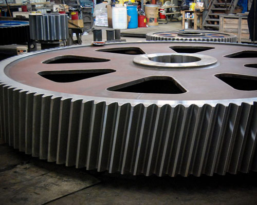
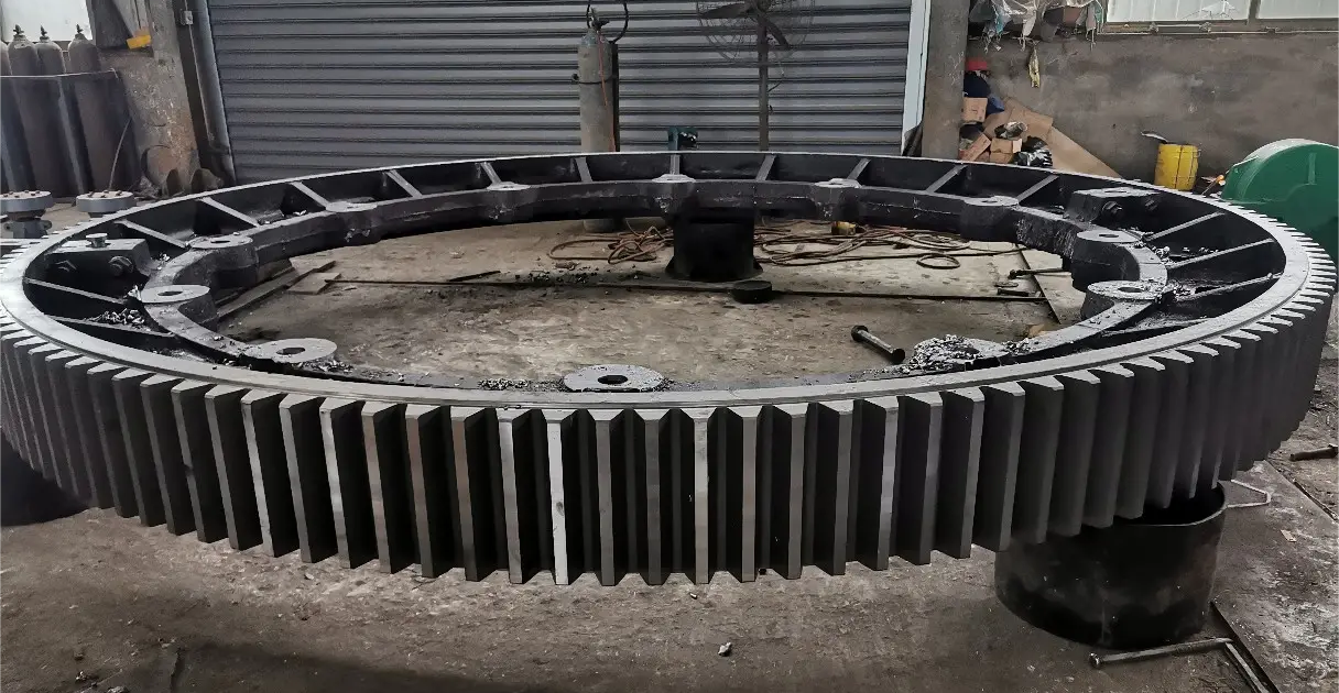
The outer teeth of the large gear ring are divided into two types of tooth shapes: drum teeth and straight teeth. It can change the contact conditions of the teeth and improve the ability to transmit torque, thereby meeting the requirements of cost protection and extending the service life. The large gear ring is a thin-walled ring forging. It is easy to have problems such as uneven wall thickness, folding, and ellipse during the forging process. Therefore, the quality of the casting can be improved by controlling the details of the casting process.
Therefore, it can be said that the large gear ring is a very important component for protecting the service life of the machine. So when the large gear is damaged, how should we repair it?
First, the steel castings should be processed. Different processing methods should be used for large gears with different degrees of damage, and the damaged parts of the large gear ring should be processed;
Then, welding should be carried out. Before welding, it should be noted that there should be no impurities such as dirty oil, rust, slag, etc. near the welding part, otherwise it will affect the welding effect;
After the welding treatment, there may still be relatively small pores or sand holes on the surface of the steel casting. After removing these defects, the area should be repaired.
After the welding treatment, the damaged large gear ring can be used normally again, which not only saves the production cost of the enterprise, but also helps to reduce the loss of resources, which can be said to kill two birds with one stone.

We want you to be satisfied. Try us!
Luoyang Hengchang Heavy Machinery Co.,Ltd.
> 丨507,Building 4,Zone A National University Science Park , luoyang city Henan province China
> 丨+8613663793011 +8615838553230
> 丨 sophie@hgb-bearing.com

