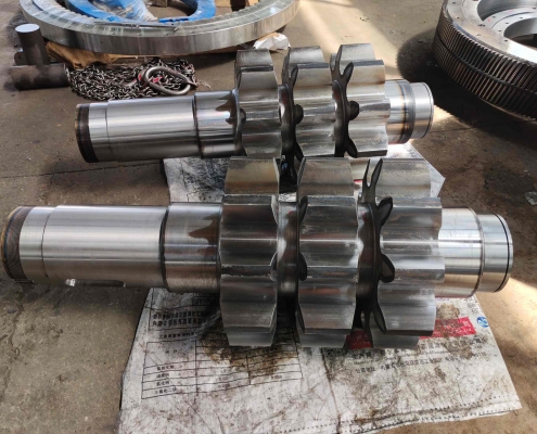
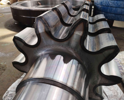
Delivery of ground gear ring and gear shaft of wind turbine

Recently, Luoyang Hengchang Heavy Machinery Co.,Ltd. cooperated with a company in the wind turbine industry to develop and manufacture a full set of main gear shaft and gear ring.

The R&D personnel adopted advanced design concepts to integrate the gearbox main shaft and main shaft bearing into the interior. Under the premise of ensuring the operating life of the equipment, the technical personnel repeatedly simulated and optimized the selection design, which greatly reduced the bearing supply cycle and purchase price.

From receiving the task to the drawing storage, from the designer’s 24-hour service production to the prototype, all data fully meet the user’s requirements and pass the whole process once. In order to shorten the manufacturing cycle, the company’s R&D, design, and assembly personnel work together, constantly explore, and overcome various processing and assembly difficulties one by one, shortening the original 5-6 months of manufacturing cycle to 3 months, and delivering high quality, high speed, and high standards to users.

If you are interested in our products, please contact us.

How to adjust the rotary kiln large gear ring during use?

Rotary kiln large gear ring processing manufacturers can produce various large gear rings according to drawings, and can ensure the product quality of large gear rings. So how should the large gear ring be adjusted during use?
1. The construction process of the rotary kiln large gear ring is as follows: divide the circle between the large gear ring and the cylinder into four equal parts, make a tool bracket for disassembly and adjustment, and fix the large gear.
Remove the bolts and locating pins at the connection of the two rings, and use a carbon arc air gouging to remove the spring sheet connecting the large gear ring to reduce the burn to the cylinder when removing the weld. After all the welds of the spring sheet are removed, use a crane to lift the two gear rings to the hard and flat ground on site, and then remove the connecting bolts between the spring sheet and the large gear ring. The connecting hole between the large gear ring and the spring sheet is re-drilled, and the bolt size is determined by the matching hole size. After the pinion and shaft are lifted and removed by the crane.
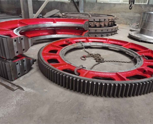

2. Correction of the rotary kiln large gear ring and spring plate. Lift the gear ring onto the prepared fixture bracket, and tighten the connecting bolts and positioning pins at the connection of the two gear rings of the large gear ring. Ensure that the joints of the two half teeth fit tightly, and use a 0.04mm feeler gauge to check around the mouth, with an insertion depth of no more than 100mm. Make two micrometer fixtures to detect the radial and end face swing of the large gear ring, divide 12 measuring points equally around the large gear ring, and use a rotary kiln to divide 12 measuring points equally around the large gear ring, record the test values, and adjust the radial and end face swing values ​​of the large gear ring through the bracket and adjustment fixture installed on the large gear ring. Now, the large gear ring has been running for several years. When adjusting, the radial and end face swing values ​​of the adjusted large gear ring should be controlled within 2.0mm and 2.5mm as much as possible under the premise of satisfying the normal operation of the large gear ring. Only after the radial and end face swing values ​​of the large gear ring are adjusted, can the connecting spring sheet be installed. The spring sheet and the barrel should be polished flat and tightly connected. The spot welding and welding of the spring sheet and the barrel should be carried out symmetrically to reduce deformation after welding.
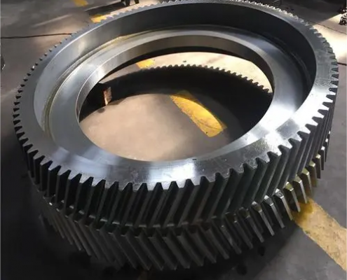

3. Correction of pinion, reducer, main motor and auxiliary motor. The clearance between the top of the pinion and the large gear should be controlled at 0.25M+(2-3)mm, the tooth surface contact, tooth height and tooth length should not be less than 40% and 50%, and the coaxiality of the pinion shaft, reducer, main motor and auxiliary motor transmission shaft should be controlled at no more than 0.2mm.
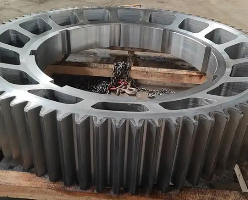
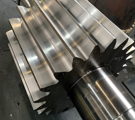
A comprehensive review of the precautions in the design of gear shaft structure!

How to choose the positioning datum for the processing technology of gear shaft?
The processing order of the main surface of the gear shaft depends to a large extent on the selection of the positioning datum. The structural characteristics of shaft parts and the position accuracy requirements of the main surface of the spindle determine that the axis is used as the positioning datum, which not only ensures the uniformity of the datum, but also makes the positioning datum coincide with the design datum. Generally, the outer circle is used as the rough datum, and the sharp holes at both ends of the shaft are used as the fine datum. Pay attention to the following points when selecting.


(1) When the relative position accuracy requirements between the processed surfaces are high, try to complete the processing of each surface in one clamping.
(2) When the top holes at both ends (such as processing the spindle taper hole) cannot be used for rough processing or positioning, in order to improve the rigidity of the process system during workpiece processing, only the cylindrical surface can be used for positioning or the cylindrical surface and the center hole at one end can be used as the positioning datum. During the processing process, the outer circle of the shaft and the center hole at one end should be used alternately as the positioning datum to meet the mutual position accuracy requirements.
(3) If the shaft is a part with a through hole, the original top hole will disappear after drilling the through hole. In order to still use the top hole for positioning, a taper plug or taper sleeve mandrel with a top hole is generally used. When the taper of the shaft hole is large (such as the milling machine spindle), a taper sleeve mandrel can be used; when the taper of the spindle taper hole is small (such as the CA6140 machine tool spindle), a taper plug can be used. It should be noted that the taper sleeve mandrel and taper plug used should have high precision and minimize their installation time. The center hole on the taper plug and taper sleeve mandrel is both the positioning reference for its own manufacturing and the finishing reference for the spindle outer circle. Therefore, it is necessary to ensure that the taper surface on the taper plug or taper sleeve mandrel has a high coaxiality with the center hole. For small and medium-sized batch production, the workpiece is generally not replaced midway after the taper plug is installed. If it is necessary to repeatedly process the outer circle and taper hole based on the other party as a reference, when reinstalling the taper plug or bushing mandrel, align or re-grind the center hole according to the outer circle.


From the above analysis, it can be seen that the selection of positioning reference in the gear shaft processing technology should consider the following process arrangements: at the beginning, the end face center hole is drilled with the outer circle as the rough reference, and the positioning reference is prepared for rough turning; rough turning of the outer circle is the positioning reference for subsequent processing: in order to prepare the positioning reference for semi-finishing and finishing of the outer circle, the front and rear top holes are first processed as the positioning reference; the gear tooth processing also uses the top hole as the positioning reference, which well reflects the principle of unified reference and the principle of reference coincidence.